The TLDR: Too busy to read? Here's a quick summary of article

Automating Complex Safety Analysis for Industrial Systems with Paitron: This article explores the partial safety analysis of the HIMax system, a critical industrial safety system with multiple digital output modules, whose signals are intended for use in a programmable electronic system.

Benefits of Using Paitron: Modelwise's Paitron streamlines the safety analysis process by automating FMEA for the HIMax system's many components and potential failure modes. This automation not only reduces workload for safety engineers by up to 80% (as seen in the HIMax case study) but also improves the accuracy of safety assessments, boosting the safe failure fraction from 99.5% to 99.8%.
Introduction
HIMA is an 800-employee company, hidden champion, and market leader specializing in safety-related automation solutions in the global process and railway industry. The electric/electronic and programmable systems produced by the company are used in a wide range of application fields, from offshore facilities to turbines. In this article, a partial safety analysis of one of their products – the HIMax – is assessed.
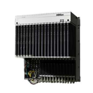
The HIMax (see Figure 1) is a “Powerful, Uninterrupted Safety Control” [1] that contains multiple digital output modules whose signals are intended for use in a programmable electronic system. The modules monitor the voltage going through and shut off when a threshold is exceeded. This feature allows to quickly detect and correct short circuits or line breaks. Moreover, the system monitors itself and gives a visual indication of its status using LEDs. Thus, the HIMax provides a convenient means for safety-critical production processes, which must run continuously and comply with various industrial standards, enabling a quick certification up to SIL3 (Process) & SIL4 (Rail).
With more than 200 components for each channel of one Digital Output (DO), the safety assessment requires an extensive analysis of over 500 possible failure modes. The assessment of the HIMax performed by HIMA consists of computing the system failure rate as the sum of its component failure rate, assuming a Diagnostic Coverage (DC) based on the standards.
In the scope of an evaluation project of Paitron [project ran on a regular Windows 10 laptop (Lenovo V155 with 4 logical processors with 2.6-3.5 GHz and 8GB of RAM)] with HIMA, a channel of the HIMax’s DO was analyzed. The DO system of the HIMax is composed of several function blocks. To determine Paitron’s limits, we studied the LSUE part of the DO. This choice has been made regarding the number (relative to the other DO’s modules) and the wide range of components the LSUE is made of.
This analysis has been performed using a “model-based” approach: the impact of each individual component failure mode on the system behavior is considered. Although such an approach is expected to provide accurate results, it is, in practice, very laborious and, in some cases, unrealistic to perform manually. This laborious aspect of the “model-based” approach is what motivated HIMA to adopt Paitron.
To overcome the workload issue, Paitron automates the study of the system’s failure modes using a numerical model. In the present publication, the LSUE model has been based on HIMA’s OrCAD Capture design.
Among the 182 possible failure modes identified for the LSUE system, Paitron automated the assessment of 146, achieving an 80% automation of the analysis within 9 hours. The remaining 20% must be verified manually by an expert, which only takes a few hours. The failure modes considered for this study and their distribution were taken from IEC 61709, and the components’ FIT rate was selected from SN 29500. Eventually, the results generated by Paitron were checked and validated by HIMA. In a more general way, the software quality of Paitron has been evaluated in a concept report with TÜV SÜD.
Analysis setup
The main purpose of the LSUE is the detection and report of overcurrent (current above 800mA). The signals emitted from this detection are used to:
- Inform the user about the overcurrent (REPORT signal)
- Trigger the shutdown of the line and protect the system integrity (CUTOFF signal)
A major step of Paitron’s safety analysis is the definition of the tracked system effects and their criticality. Knowing the system’s main purpose, the system’s studied effect criticalities (see table below) are determined regarding IEC 61508 (2010).
Table 1: LSUE studied effects and their associated criticality
| System effect | Description | Criticality |
| REPORT signal: no overcurrent indication | The REPORT signal does not report overcurrent when overcurrent occurs | Dangerous |
| REPORT signal: erroneous overcurrent indication | The REPORT signal reports an overcurrent, although no overcurrent occurs | Safe |
| REPORT signal: undetermined state | The REPORT signal is neither high nor low | Safe |
| REPORT signal: overvoltage | The REPORT signal is overvolted | Dangerous |
| CUTOFF signal: no overcurrent indication | The CUTOFF signal does not report overcurrent when overcurrent occurs | Dangerous |
| CUTOFF signal: erroneous overcurrent indication | The CUTOFF signal reports an overcurrent although no overcurrent occurs | Safe |
| CUTOFF signal: undetermined state | The CUTOFF signal is neither high nor low | Dangerous |
| LSUE: no output voltage | The LSUE output is stuck low | Safe |
Failure modes, effects and diagnostic analysis
With 41 components and considering IEC 61709, “model-based” safety analysis of the LSUE system requires the study of 182 (see Figure 2) failure modes, among which Paitron:
- Identified 156 possible failure modes of the system
- Was able to propose a model of the system for 152 fault cases
- Successfully evaluated the effects of 146 of the system’s failure modes
The only components Paitron was not able to study are the integrated circuits. Indeed, the failure modes of integrated circuits were not available in the tested version of Paitron, which deeply decreased the automation rate of the study. The failure modes of the integrated circuits represent the 26 missing failure modes (182-156 failure modes) that Paitron was not able to identify, model, and simulate.
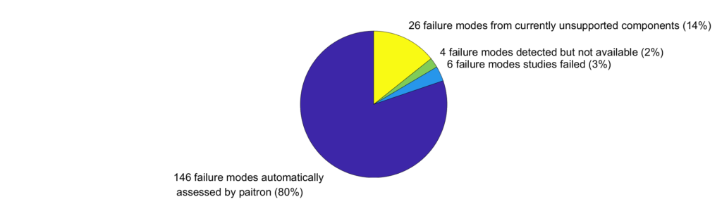
The analysis performed by Paitron lasted 9 hours and allowed to cover 80% of all the failure modes to be considered for such an analysis. In 6 cases (152-146 cases), the simulation of a failure mode crashed or did not converge (within 5 minutes) for one or several of the system’s inputs. Such cases are indicated in Paitron’s generated results with the mention: “<not studied, check manually>”.
A view of the FMEDA sheet generated during this study is given below in Figure 2. Paitron’s analysis allowed to determine the LSUE safety metrics (see Table 2 and Table 3) within a realistic amount of time:
- 9 hours for automatically evaluating the effects of 146 failure modes;
- the time needed to complete the manual analysis for the 36 remaining cases (182-146 cases). This represented a few hours of work (i.e., 2hrs).
From the above runtime, we can estimate that the full analysis of the system would take approximately 11 hours if all the components of the LSUE and their associated failure modes were present in Paitron’s database.
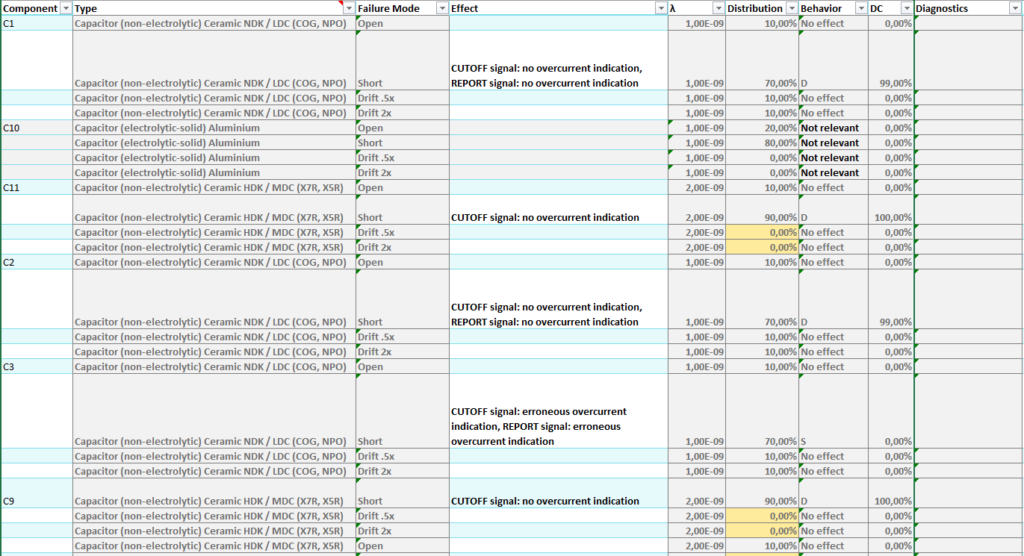
Table 2: Safety metrics of the LSUE evaluated using Paitron
| Metric | Results |
| Safe Failure Fraction (SFF) | 99,77% |
| Safety Function Failure Rate [1/h] | 44.8 FIT |
| Device Failure Rate [1/h] | 48.8 FIT |
| Mean Time Between Failure (MTBF) [h] | 2339 years |
As we can see in Table 3, the results found using the “model-based” approach are different than those found when using assumptions from the standards (e.g., for Diagnostic Coverage). These differences highlight that the results found using assumptions can be considerably refined and testify to the considerable interest in the “model-based” approach to treat such safety analysis problems. The results of both approaches are compared in the table below. For the DO of the HIMax, HIMA’s experts assume 50% of the cases result in a dangerous failure. Having a diagnostic coverage of 99% with respect to ISO 61508 enables HIMA to achieve a safe failure fraction of 99.5%.
Table 3: Comparison of the failure rates assessed by HIMA (“part counting” method) and Paitron (“model-base” method)
| Failure rate | HIMA | Paitron |
| Safe Detected | 24.16 | 15.00 |
| Safe Undetected | 0.24 | 2.96 |
| Dangerous Detected | 24.16 | 18.23 |
| Dangerous Undetected | 0.24 | 0.10 |
| No effect | 0.00 | 8.48 |
| Not relevant | 0.00 | 4.00 |
| Total | 48.80 | 48.80 |
Our analysis with Paitron allowed us to re-estimate the safe failure fraction to be approximately 99.8%. This means a reduction of the most critical case, “Dangerous Undetected” by 58.3%. Additionally, roughly a fourth of the failure modes could be classified as either “Not relevant” or having “no effect” on the system’s safety.
Conclusions and further work
The safety analysis presented showcased an application of Paitron for an industrial safety control unit. Paitron relies on the “model-based” approach, which was easily embedded within HIMA’s processes & workbench by integrating existing OrCAD Capture models. Within the project, it was shown that the analysis with Paitron is more accurate than the method currently used by HIMA. HIMA’s experts calculated the safe failure fraction to be 99.5%. Our analysis with Paitron allowed us to re-estimate the safe failure fraction to be approximately 99.8% – cutting the residual failure rate in half.
“The quality of the analysis improves extremely”
Feedback from the responsible Functional Safety Engineer Sven Sulzbach.
A better understanding of the system allows for improving the system by “discovering and controlling all failures” (Markus Dalheimer, Functional Safety Engineer) and achieving a diagnostic coverage above 99% to which HIMA is currently bound by the standards. Furthermore, using Paitron is beneficial during design as it enables engineers to directly check their design during the early stages of the development – even without a safety expert’s involvement.
“No human could do 23.000 checks in 40 minutes”.
Jochen Däschler, Functional Safety Expert at HIMA impressed by how direct the feedback was.
This would not only reduce the number of design iterations before reaching the desired safety level but also reduce the amount of work for safety engineers. Analyses that previously took multiple weeks can now be done within a few days. The latter is important with the lack of safety engineers on the market, reflected in Jochen Däschler’s statement that “HIMA aims at enabling their designers to perform expert analyses”.
The main hurdle met by Paitron was the consequent number of integrated circuits contained in the HIMax. Indeed, the version of Paitron used in this study (1.7) lacks the failure modes of such components, which subsequently reduced its automation rate. In the study, the failure modes of the integrated circuits represent 14% of the system’s failure mode. This observation highlights the importance of modelwise GmbH to provide the possibility to account for the integrated circuit’s failure mode in future versions. Beyond this aspect, the possibility of using Paitron on dedicated computation servers could reduce analysis time and act as a spell-checker for engineering designs providing feedback within milliseconds.
Paitron is used to detect the exact cause for which the system requirements are violated when facing a failure mode and prevents safety engineers from human error due to the repetitive nature of the “model-based” safety analysis. The data generated by Paitron can be used for safety proofs or to speed up a product certification. Additionally, all intermediate data generated by Paitron is openly accessible to versioning and documentation systems.
The following summarizes the key benefits of Paitron:
- Accelerate the time to market by weeks
- Enable designers to perform expert analyses
- Catching design flaws early on saves 80% of the costs of fixing
Ready to streamline your FMEA process and achieve similar efficiency gains for your industrial safety-critical systems? Contact us today to learn more about Paitron or request a free demo!
Comments, suggestions? Brickbats, bouquets? Please send your feedback to our editor.
Additional Resources
References
[1] “HIMax,” Products & Services | HIMA Paul Hildebrandt GmbH. [Online]. Available: https://www.hima.com/en/products-services/himax [accessed 10.01.2022]
Project Toolkit
- A regular Windows 10 laptop (Lenovo V155 with 4 logical processors with 2.6-3.5 GHz and 8GB of RAM)
- Safety Assessment Automation: Paitron V1.7 (1.7.7971.31144)
- Modeling: OrCAD Capture V17.3
