Introduction
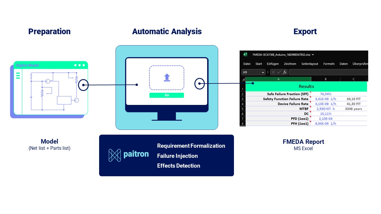
Paitron is a software solution for (partially) automated model-based functional safety analysis exploiting logical or physical models. The current version of Paitron supports both Failure Mode Effects Analysis (FMEA) and Failure Mode Effects and Diagnostics Analysis (FMEDA). The results of the analyses are stored and presented in Excel files.
Paitron applies techniques from model-based and qualitative reasoning (subfields of automated reasoning in artificial intelligence). Model-based means that the reasoning is based on formally represented models of the system being developed, while qualitative characterizes the type of models that are based on systematic abstractions of system behavior.
Functional Description
System Requirements
Supported Operating Systems:
- 64-bit editions of Windows 7 SP1, 8.1, 10 and 11
For performing automated functional safety analysis, Paitron will exploit third-party simulation tools, such simulation tools must be installed on the same computer as Paitron. Without connected simulation software, Paitron can still create FMEDA tables and compute safety metrics. The list of currently supported tools and their versions is given in Table 1. Additionally, the third-party software required for using Paitron is listed in Table 2 in the Appendix.
Features
Automation of functional safety analysis, especially failure propagation and failure mode and effect analysis (FMEA) is achieved with the following workflow:
1. Import system design:
The first step is the import of design drafts (circuit design, netlists or similar models). The data interfaces used in the software enable exchange with simulation tools. A list of simulation tools interfaced by Paitron can be seen in Table 1.
2. System formalization:
The system editor enables the formalization of a system and can be accessed via the “Formalize” button on the main screen. The system information should specify relevant input, output, and optionally included effects. This involves defining terminals (inputs and outputs) and their domains (possible values or ranges).
The requirements are formulated using constraint templates, which may involve establishing thresholds or expected behaviors for system variables.
Using the deviation effects enables the user to skip the requirements formalization, as the expected outputs are generally checked for deviations.
Scenarios correspond to different possible system configurations (e.g., take-off, cruise, landing) under which the system is studied. It is not required to define any scenarios; they can be used when the system needs to be studied only in certain contexts.
Remark: The variables, domains, and scenarios are only available for models that contain behavioral information (usually these are the models that can be simulated).3. Component matching:
Configure parts opens a new window with the list of the system’s components.
- Manual matching:
For each component, the user can specify the exact type (e.g. a diode can be LED, Zener, Schottky,…) and impose the failure mode and rate to apply to the component.
- Bill of Material (optional):
After importing the bill of material (BOM) from the user’s Computer Aided Engineering (CAE) or Electronic Design Tool (EDA) software, the software automatically matches the recognized components with components from the Modelwise model library (see Table 3 for an overview of failure modes, which can be automatically assessed). Supported BOM formats are .exp and .txt.
If you do not provide a netlist, just the BOM does not provide clear information on the connections between components, thereby failure propagation is omitted.
As the model library gets continuously extended (on a weekly basis), contact support@modelwise.ai to get an up-to-date list of the library.
Remark: The BOM field mappings and rules need to be defined in order to correctly identify the system parts and their failure rate/modes type from the BOM information. Contact the support team to discuss the procedure (support@modelwise.ai). 4. Analyze:
As soon as the analysis definition is completed, the analysis is ready to be started by Paitron. Navigate to the desired system and click on “Analyze”. The choice is then given to the user to either perform an FMEA or an FMEDA analysis.
In the case of an FMEDA, the user has an option between FMEDA according to IEC 61508 or ISO 26262.
5. Failure injection:
Failure injection is the process of generating a model of a system with a particular failure. It is performed automatically by Paitron when an FMEA or FMEDA analysis is started. Standards for failure modes, that are integrated with Paitron, can be seen in Table 4.
6. Model abstraction:
Each of the failure modes is simulated to generate the behavior of the system. The simulation results are converted into a formal representation of the system.
7. Effects detection:
The SMT solver tests whether all specified effects (specifically, their conditions) can occur under the introduced failure modes.
8. Export:
The result of the evaluation is presented in an FME(D)A table which should contain all failure modes (according to the selected standard; see restrictions in Table 4). The evaluation of the failure effects is mostly (>80%) automated, including the criticality (safe or dangerous). Based on the finalization by the user (evaluating the <20% not automatically generated failure effects, which are clearly marked with the statement “not evaluated, check manually”), the associated metrics and failure modes are calculated.
9. FMEDA manager:
Shows the components failure modes and failure rates in the considered FMEDA sheet, and supports change management, as well as individualization.
In the Paitron GUI, click the report image to open the desired report. After loading the report, a new window opens which shows the selected component failure rates and modes in the considered FMEDA sheet. The failure rate and modes can be selected from the source used in the FMEDA. Paitron will recommend you the components that are the most likely to be used based on the selected reference type (“Ref. Type”) by highlighting them in green. Allows to add new components, and to customize FIT rates and Failure modes for the respective FMEDA sheet.
Appendix
Appendix A: Tables
Table 1: List of simulation tools interfaced by Paitron
| Software | Version | Note | Supported File Formats |
| Xpedition | VX2.14 and later | License for AMS 200 is required | .cmd |
| LTspice XVII | XVII, 17 and later | When both 17.* and XVII are installed, by default the 17.* will be preferred | .asc, .net, .cir, .sp |
| OrCAD PSpice Designer | 17.2 and later | .sim, .net, .cir, .sp | |
| Altium Designer | 22.3 and later | Through ngspice | .nsx, .net, .cir, .sp |
| CircuitStudio | 1.5 and later | Through ngspice | |
| Matlab | R2018a and later | Including Simulink and Simscape | .slx |
Table 2: List of third-party software used by Paitron
| Software | Version | Note |
| .NET Desktop Runtime | 6.0.5 | Included in the installer |
| ngspice | 36 | Embedded in the software |
| Microsoft Excel | 2013 SP1 or later |
Table 3: Overview of failure modes, which can be automatically analyzed
| Component Type | Failure Modes (IEC 61709) | Failure Modes (MIL-HDBK-338B) |
| Resistors | Short Circuit, Open Circuit, Drift 1 | Short Circuit, Open Circuit, Drift |
| Capacitors | Short Circuit, Open Circuit, Drift | Short Circuit, Open Circuit, Drift |
| Inductive Devices/Coil | Short Circuit, Open Circuit | Short Circuit, Open Circuit, Drift |
| Transistors | Short Circuit, Open Circuit | Short Circuit, Open Circuit, Drift |
| Optocouplers | Short Circuit, Open Circuit, (Drift is missing) | N/A |
| Digital Integrated Circuits | Open Circuit | N/A |
| Relays | Short Circuit, Open Circuit | Not modeled |
| Diodes | Short Circuit, Open Circuit, Drift, Forward leakage current drift | Short Circuit, Open Circuit, Drift |
| Light emitting diodes | Short Circuit, Open Circuit | check |
| Photodiodes | Short Circuit, Open Circuit | N/A |
| Further Components 2 | – | Short Circuit, Open Circuit |
Table 4: List of failure rate and mode sources available in Paitron
| Source name | Reference | Failure rate | Failure mode | Fully digitized? | Missing Information |
| SN29500 | SN 29500, Failure rate, component, expected value, dependability, Siemens, Note 1, 2016. | Yes | No | No | Calculating the failure rate in operating conditions for Integrated Circuits |
| IEC61709:2017 – Annex A | IEC 61709, Electric Components -Reliability -Reference Conditions for Failure Rates and Stress Models for Conversion, International Electrotechnical Commission, 2017 | No | Yes | No | Failure modes for: – Optocoupler: Drift – Digital Integrated Circuits: All FMs – Light emitting diode modules: All FMs – Laser diodes and modules: All FMs |
| MIL-HDBK-217F | MIL-HDBK-217F, Reliability Prediction of Electronic Equipment, Department of Defense – United States of America, 1991 | Yes | No | Yes | – |
| MIL-HDBK-338B | MIL-HDBK-338B, Electronic Reliability Design Handbook, Department of Defense – United States of America, 1998 | No | Yes | Yes | Failure modes without an impact on the electrical behavior |
1 Components parameter value (resistance, capacitance, etc.) is either doubled or halved
2 Battery, Cable, Connector/Connection, Printed Wiring Assembly, Solenoid