The TLDR: Too busy to read? Here's a quick summary of article

FMEDA of Arduino power supply stage: The article presents a Failure Modes, Effects, and Diagnostic Analysis (FMEDA) of the power supply module of an Arduino™ UNO Rev3 to evaluate its design robustness and estimate its lifespan when powered continuously.

Results: The results show that a component failure affecting the operation of this board’s stage is very rare (approximately every 1400 years), while the system's safe failure fraction is approximately 58%. Based on this information, the article estimates that the Arduino's power supply stage could qualify for SIL 2 (Safety Integreity Level).

Recommendation: The article recommends using the power jack and USB together for the board's supply to minimize the risk of Arduino power interruption.
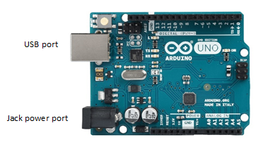
An Arduino is a good starting point for learning electronics or prototyping. Indeed, the board was designed to provide an inexpensive and easy way for hobbyists, students, and professionals to create devices that interact with their environment using sensors and actuators [1]. Among other things, the simplicity of use of an Arduino is remarkable for its powering options: the board can be supplied by a power jack or directly by the USB port used to program the board.
Although the Arduino power selector stage ensures protection against simultaneous powering, the components of this stage are not spared by wear and construction defaults. In this article, Failure Modes, Effects, and Diagnostic Analysis (FMEDA) of the power supply module of an Arduino™ UNO Rev3 is presented to assess its design’s robustness and estimate its lifetime when being uninterruptedly powered. The following analysis is based on the process industry standard for the functional safety of electrical, electronic, and programmable systems (E/E/PS) systems:
- IEC 62061 for components failure modes;
- SN 29500 (Siemens’s standard) for components failure rates;
- IEC 61508 for the application of the above-mentioned standards and the SIL determination.
Powering input specification and modeling
The Arduino™ UNO Rev3 can be powered via:
- the power jack with a [7.00; 12.00] V voltage (datasheet recommended voltage);
- or the USB port with a [4.40; 5.25] V voltage (USB min/max power pin voltage).
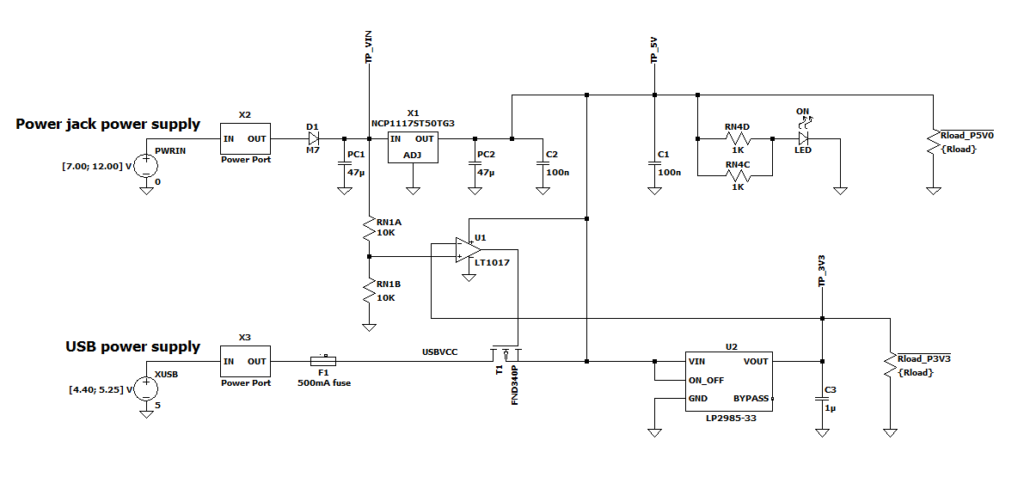
When supplied simultaneously by a power jack and USB, the Arduino board will favor the power jack input voltage to supply the board. The input power selection is made through the use of the T1 MOSFET and U1 comparator (see Figure 2).
A 500mA fuse (F1) is connected to the USB power pin to protect the board from overcurrent.
A visual indication of the board being powered is given to the user through the lightning of a green light emitting diode (ON LED). The overall system behavior is summed up below:
| Power jack port | Power USB port | +5V voltage | +3.3V voltage | ON diode |
| [7.00; 12.00] V | Disconnected | ~5V | ~3.3V | ON |
| Disconnected | [4.40; 5.25] V | ~5V | ~3.3V | ON |
| [7.00; 12.00] V | [4.40; 5.25] V | ~5V | ~3.3V | ON |
| Disconnected | Disconnected | 0V | 0V | OFF |
The power supply stage of the Arduino™ UNO Rev3 has been modeled and simulated using LTspice®, a SPICE simulation software provided by Analog Devices. The circuit model (see Figure 2) was built from the circuit diagram provided by the Arduino company [3].
Load resistances (Rload_P5V0 and Rload_P3V3) have been added to the +5V and +3.3V output of the circuit to model the impedance of the circuit to which the Arduino power supply stage is connected.
Failure mode effects
The effects of the component failure mode on the system are associated with a criticality (safe or dangerous):
- The safe effects: It will result in a minor functional default but won’t prevent the Arduino board from working autonomously. For instance, an erroneous indication of the ON diode is not considered as dangerous. Melting of the fuse F1 is considered safe since it does not prevent the board from being powered (in such a case, the power jack can still be used).
- The dangerous effects: It will endanger the integrity of the board and may entail dangerous situations for the user. For instance, the overcurrent of the ON diode or overvoltage of the integrated circuits is considered as dangerous.
In total, a list of 8 effects are tracked:
| S. No. | System effect | Description (Example of induced treat) | Criticality |
| 1 | ON LED stuck off | The ON LED is always off. | Safe |
| 2 | ON LED destruction by overcurrent | The ON LED is destroyed by overcurrent (Risk of fire). | Dangerous |
| 3 | Fuse melting | The fuse F1 melts because of overcurrent. | Safe |
| 4 | +5V output low when board powered | The +5V output of the power supply stage is low when the Arduino board is correctly supplied by Jack and/or USB. | Safe |
| 5 | +5V output overvoltage | The +5V output of the power supply stage is too high, which may damage the Arduino board (Risk of fire or destruction of the Arduino board). | Dangerous |
| 6 | +3.3V output low when board powered | The +3.3V output of the power supply stage is low when the Arduino board is correctly supplied by Jack and/or USB. | Safe |
| 7 | +3.3V output overvoltage | The +3.3V output of the power supply stage is too high, which may damage the Arduino board (Risk of fire or destruction of the Arduino board). | Dangerous |
| 8 | 5V voltage regulator (NCP1117) incorrect supply | The NCP1117 voltage regulator is supplied out of its recommended input voltage range [6.50; 12.00] V (Risk of fire or destruction of the component). | Dangerous |
Failure modes effects and diagnostic analysis
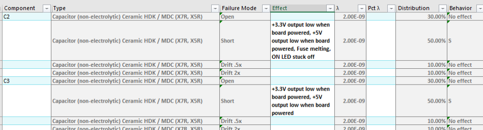
Over the 74 failure possible modes listed for the Arduino’s power supply stage, 40 are found to lead to system effects, among which 12 are considered dangerous. The study of 46 of the failure mode effects was automated, leading to an automation rate of 62%. A view of the FMEDA sheet generated during this study is given in Figure 3 (please contact support@modelwise.ai for the detailed FMEDA result sheet).
Based on the above-cited norm and the provided circuit, a safe failure fraction (SFF) higher than 58% is found for the Arduino power supply stage, while the system is expected to fail around every 1375 years, as highlighted in the table below:
| Safe Failure Fraction (SFF) | 58.35% | |
| Safety Function Failure Rate [1/h] | 7.90E-08 | FIT: 79 |
| Device Failure Rate [1/h] | 8.30E-08 | FIT: 83 |
| Mean Time Between Failures (MTBF) [h] | 1.20E+07 | 1375 years |
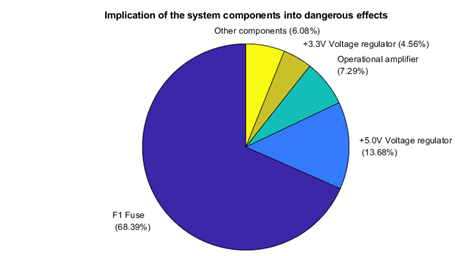
More precisely, we found that the dangerous effects are mostly brought by the failure modes of the fuse (approx. 68%), followed by the 5V voltage regulator (approx. 14%) and the operational amplifier (approx. 7%) as depicted below:
Although the dangerous failure rate of the system (34.6 FIT = (1- SFF)*Device Failure Rate) is good enough to pretend to be the Safety Integrity Level (SIL) of class 3 or 4, its safe failure fraction is too low for such a qualification assuming a hardware fault tolerance (HFT) of 0. Indeed, for a 0 HFT, SIL 3 requires an SFF of at least 90%, which leads the Arduino power supply stage to qualify for SIL 2.
Conclusion
The Failure Modes, Effects, and Diagnostic Analysis (FMEDA) presented in this study aimed to assess the robustness and lifetime of the Arduino™ UNO Rev3 power supply stage. The investigation performed in this study aimed to explore the system’s design, assuming single points of failure and helped us to identify the main contributors to dangerous effects. From these results, we were led to conclude that a component failure affecting the operation of this board’s stage is very rare (roughly every 1400 years), while the system’s safe failure fraction is approximately 58%. Regarding this information, we estimated that Arduino’s power supply stage could qualify for SIL 2.
As visible in Figure 4, the F1 fuse of the system is the most problematic component for the Arduino powering for the slow and fail-to-open failure modes due to overcurrent. We recommend using the power jack and USB conjointly for the board’s supply to reduce the risk of Arduino powering interruption.
Comments, suggestions? Brickbats, bouquets? Please send your feedback to our editor.
Additional Resources
References
[1] Louis, Leo. (2018). Working Principle of Arduino and Using it as a Tool for Study and Research. International Journal of Control, Automation, Communication and Systems.
[2] Arduino.cc. 2023. Arduino – ArduinoBoardUno. [online] Available at: https://www.arduino.cc/en/Main/arduinoBoardUno [Accessed 25 October 2023].
[3] Arduino.cc. 2023. Arduino UNO Rev3 circuit schematics. [online] Available at: UNO-TH_Rev3e.sch (arduino.cc) [Accessed 25 October 2023].
